|
1
|
- Captain Charlie Johnson, PE
- JTB Marine Service
- St. Petersburg, FL
- cjohnson@jtbmarine.com
- 727.323.2500
|
|
2
|
|
|
3
|
- This presentation will not make you into a competent marine electrician
- JTB Marine Corporation and the presenter assume no responsibility for
the use of any of the materials, calculations or methods described in
this presentation.
|
|
4
|
- Mechanical Engineer
- Retired Naval Engineer: Submarine Maintenance and Repair
- 100 Ton Master
- ABYC Certified Marine Electrician
- Amateur Radio Operator: Advanced License
- Live aboard a 53’ Gulfstar Trawler; ten years
- Extensive cruising experience; three years “Down Island mon” in the
Eastern Caribbean
- All round nice guy……..
|
|
5
|
- System Design
- Equipment Selection
- System Installation
|
|
6
|
- The Energy Equation:
- Energy In = Energy Out Plus Inefficiencies
|
|
7
|
- The Energy Equation Restated:
- Sources of energy = Users of energy plus inefficiencies
|
|
8
|
- On today’s yacht:
- What are some sources of energy?
- What are some users of energy?
- What inefficiencies are encountered?
|
|
9
|
- Load calculations
- Battery bank sizing
- Wiring considerations
- Circuit protection devices
- Switches
|
|
10
|
- Be brutally honest...do not hedge your numbers!!
- The goal is to arrive at the realistic amount of power that your battery
bank is going to have to produce to supply your 120 VAC loads.
|
|
11
|
- First some definitions:
- Energy is a measure of the ability of a system to do work; the units
are watt-hrs
- Power is rate of energy delivery; the units are watts
- One thousand watts are equal to one kilowatt
- The discharge cycle is the amount of time that the house bank will be
providing energy to the normal 12 VDC loads and the inverter before
being recharged
|
|
12
|
- …and now some simple mathematics:
- Power equals voltage x current
- (Watts) = (Voltage) x (Current)
|
|
13
|
- Example:
- Label plate on the new FRAMUS states:
- Voltage: 120 VAC
- Frequency: 60 Hz
- Current: 1.5 amps
- What is the power consumed by the new FRAMUS?
|
|
14
|
- Recalling our formula:
- Power equals voltage x current
- …and substituting for V and I, we get:
- P=120 VAC x 1.5 amps
- =180 watts
|
|
15
|
- The instantaneous power consumption of the FRAMUS is 180 watts…
- …however we need the estimation of the duration that this appliance will
be used in order to calculate the energy (watt-hours) requirement
|
|
16
|
- This part is easy; the energy requirement is simply the power
requirement multiplied by the duration of use
|
|
17
|
- Continuing with our example; the Admiral is going to use the FRAMUS for
one hour per discharge cycle
- The energy consumed will be:
- Energy=power x time of usage
- Therefore; the energy requirement is:
- E=180 watts x 1 hour = 180 watt-hours
|
|
18
|
- Repeat this process for all of your 120 VAC loads
- Most of the standard texts have estimates if you cannot find the label
plate data
- A simple spreadsheet would be helpful
- Remember…no cheating!!
|
|
19
|
|
|
20
|
|
|
21
|
- In a perfect world, energy conversion would take place with 100 %
efficiency…there would be no losses
- In our real world, we have to account for losses
- Recall that our 120 VAC loads were calculated to be 7,032 watts; or
about
- 7 kW
|
|
22
|
|
|
23
|
- …a little more mathematics:
- Energy out = Efficiency x Energy in
- Solving for Energy in:
- Energy in = Energy out /Efficiency
- So, for our example:
- Energy in = 7,000 watts/0.85
- = 8,235 watts
|
|
24
|
|
|
25
|
- Converting Watts
amp-hours
- Recall that: Power = volts x amps
- And: Energy = Power x time
- Therefore: Energy = volts x (amps x time)
- The amp-hour concept is handy to introduce:
- One amp being consumed for one hour is one amp-hour
|
|
26
|
- Continuing with our example:
- Initial Battery Loads = Energy in/12 VDC
- = 8,200 watts/12
- = 683 amp-hour
|
|
27
|
- This is only for the 120 VAC loads supplied by the inverter…
- Must add normal hotel loads for the 12 VDC appliances aboard
- Again, be brutally honest…a spreadsheet approach can help
- For our example; I am assuming 117 amp-hours of 12 VDC load
|
|
28
|
- The Final Battery Loads =
- 683 amp-hours + 117 amp-hours
- (120 VAC loads) (12 VDC loads)
- = 800 amp-hours
- This is not a day sailor!!
|
|
29
|
|
|
30
|
- Some practical considerations…
- Deep cycle batteries live longest if you only discharge them to 50% of
their total capacity
- Getting the last 15% of a battery’s capacity back into the battery
takes a disproportionate amount of time
|
|
31
|
|
|
32
|
- We arrive at the ideal battery capacity (C) with a little more math:
- Battery Loads = (0.5-0.15)C
- Solving for C:
- C = Battery Loads / 0.35
|
|
33
|
- The Ideal Battery Bank for our example would be:
- C = 800 amp-hrs/0.35
- = 2,286 amp-hrs
|
|
34
|
- Considering only flooded, true deep cycle batteries…
|
|
35
|
|
|
36
|
- Direct Current Connections
- Heavier is better
- Use the 3% voltage drop tables
- Use only Tinned Boat Cable
- BC5W2
- Insulation rated for 105°C dry
- Insulation rated for 75° C wet
- UL 1426
- Type 3
|
|
37
|
- Direct Current Connections
- Do not use SAE Boat Cable
- On average; approximately 12% less cross-sectional area for the same
wire gage
- Use properly sized, tinned, closed end lugs
- Crimp lugs using a box crimping tool
- Do not us hammer blow type crimpers
- Use heavy duty heat shrink on lugs
|
|
38
|
- If the tables don’t allow for the expected current; calculate using this
formula:
|
|
39
|
- Where:
- CM is the req’d. circular mil area of the conductor
- K is a constant regarding the properties of copper, 10.75
- I is the current in amps
- E is the voltage drop; a 3% voltage drop in a 12 VDC system is 0.36
- L is the round trip conductor length in feet
|
|
40
|
- For a sample calculation, assume the following:
- The maximum current will be 200 amps
- The round trip from the B+ bus bar to the inverter/charger and back to
the B- bus is 18 feet
- 3% allowable voltage drop; 0.36
|
|
41
|
- Calculating the required CM:
- CM = 10.75 x 200 amp x 18 ft
- 0.36 volts
- CM = 107,500
|
|
42
|
|
|
43
|
- From Table XII, we need 2/0 cable
- We need to check to see if 2/0 cable with 105°C insulation can handle
this kind of load in the engine room.
|
|
44
|
|
|
45
|
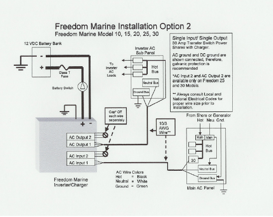
- Alternating Current Connections
- Use BC5W2 three conductor AWG #10
- Run a separate case grounding wire (safety green wire) from the
grounding stud provide on the inverter/charger to the 120 VAC safety
ground bus
|
|
46
|
- Install a Class T fuse of the size specified by the manufacturer within
7 inches of connection to the B+ bus
- If the conductor is sheathed, the fuse can be a maximum of 40 inches
from the connection to the B+ bus
|
|
47
|
- Install a remotely accessible
inverter/charger disconnect switch in the B+ conductor
- Ensure that the output from the inverter is protected so that the boat’s
120 VAC power panel can only be supplied by ONE SOURCE at a time
|
|
48
|
|
|
49
|
- Inverter/Charger
- Sine wave or modified sine wave
- Charger requirement
- Charging starting batteries
- Battery Isolators
- Battery Combiners
- Echo Charging
- Battery Monitoring System
- One bank or two
- Used to control inverter/charger…or not
|
|
50
|
|
|
51
|
- With the possible exception of the main engine starter, an
inverter/charger is the largest 12 VDC load on the entire boat
- Wiring and installation MUST be workmanlike to the extreme…serious
problems can occur if corners are cut
- If you do not have the requisite skill, tools and material to properly
install the inverter/charger…do not attempt to do it yourself.
|
|
52
|
- There are real design issues that have to be considered on how to route
120 VAC power to and from the inverter/charger
- If you are not comfortable working on alternating current circuits, hire
a knowledgeable ABYC Certified Electrician and help him so you can
learn.
|
|
53
|
- Alternating current can KILL YOU DEAD.
|
|
54
|
- If you are not comfortable working on alternating current circuits, hire
a knowledgeable ABYC Certified Electrician
- Work with the Electrician and learn some of the techniques for wiring
alternating current circuits
|
|
55
|
- This presentation did not make you into a competent marine electrician
- JTB Marine Corporation assumes no responsibility for the use of any of
the materials, calculations or methods described in this presentation.
|
|
56
|
- This presentation has provided you with:
- the information that you need to
ensure that your inverter/charger is designed properly
- some of the details to ensure that the installation is properly
installed
- If you are the least bit uncomfortable with dealing with extremely large
amounts of DC energy or the 120 VAC system….
|
|
57
|
- Engage the services of an ABYC Certified Electrician and discuss your
planned installation using this presentation as a guide….
|
|
58
|
- References
- ABYC Standards and Technical Information Reports for Small Craft
- Boatowner’s Mechanical and Electrical Manual; 2nd Ed.; Nigel
Calder
- Powerboater’s Guide to Electrical Systems; Ed Sherman
- Blue Sea Systems; http://www.bluesea.com/
- Xantrex; http://www.xantrex.com/
|
|
59
|
|

 Notes
Notes